


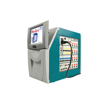
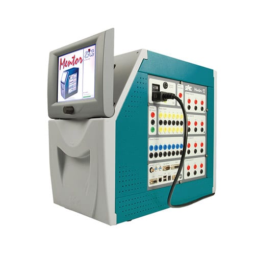
Mentor-12
Universal Relay Testing System
ADVANCED TEST FUNCTIONS
The most complete Built-in Test functions, with on-screen graphic configuration, to carry out typical test for protection relays and protection schemes. These tests allows determining the state of the relay and obtaining readings and results of different relay parameters under different test conditions, configured by the user. A Logger is available for all functions, to carry out an in-depth study of the performance of the relay tested throughout the function.
Universal Three-phase Protective Relay Test Set
The Mentor 12 is the most advanced three-phase relay test set available for type and field testing of electromechanical and digital protections of any kind, in traditional or IEC-61850 based substations.
CHARACTERISTICS
- Stand-alone functionality, without pc
- Easy and intuitive touch screen
- Up to 12 currents and up to 6 voltages
- Modular concept, adapted to user needs
- Voltages convertible to current
- Advanced built-in test tools
- Iec 61850 testing capabilities
APPLICATIONS
- Secondary current injection testing.
- Protection relays testing.
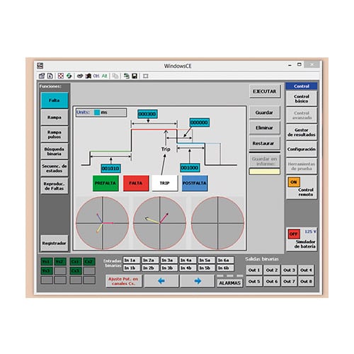
Fault function: This three-state function allows the user to set a complete simple fault and execute the prefault, fault and postfault values, including duration of the states, logic I/O states, and trip conditions. The fault execution displays the progress timeline and test results in graphical and numeric mode, including the trip time and end function time.
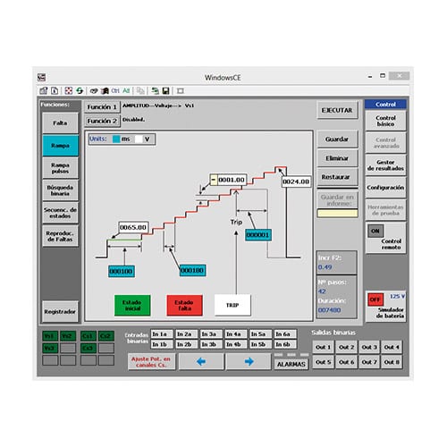
Ramp function: Single and Double Ramps, upward or downward ramps, of any output parameter on the MENTOR 12 can be programmed and executed. Ramp function operation is provided for finding limiting values, such as pick-up and drop-off. The linear ramp is the best way of handling parameters such as the Phase Angle, Voltage and Frequency, especially the latter, as the real performance of these parameters can be reproduced with great precision.
The flexibility of this module allows two synchronized simultaneous ramps of different variables, each one applied to different types of output quantities. For example, one ramp moving the Voltage and the other moving the Current (Impedance ramp), or applied to the same selected output source. For example one ramp moving the voltage and the other moving the frequency at the same time (V/Hz variation ramp).
After ramp and trip conditions are set, the test progress is displayed in an oscillographic fashion, with electrical values evolving along the ramp and trip events being stamped on the timeline as they take place. Relay trip time, trip value and duration of the test are displayed, and test repetition can also be performed if desired, or with different conditions. At the end of a test, user can type a name and a brief description and save it for future use. Since storage takes place on removable USB pendrives, the capacity is unlimited, and it also provides a way to create a collection of automatic test routines.
Pulse Ramp function: It is a way of carrying out a Fault ramp, each state with its pre-fault and its fault. The basic difference is that instead of continuously increasing the magnitude, a preset condition state occurs between consecutive pulses. This function is preferably used when instantaneous or defined time values are sought in Overcurrent elements, as it enables to inject a high current value during a specified time and return to low current conditions or even non-existing current conditions between each programmed pulse, thus eliminating the possibility of damaging the relay tested.
It is also very useful to verify trip setting values in protection zones, as we can enter the zone for a defined time and exit it without causing the other slower zones to trip.
The information about the number of steps (increases) and the total function length (in milliseconds) appears automatically calculated in the screen, as in the ramp function.
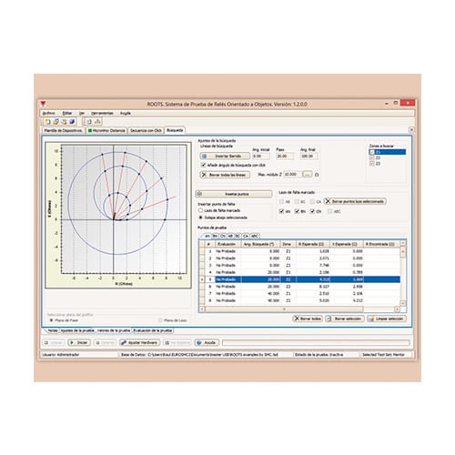
Binary Search function, unlike the ramps, the Binary Search does not use a fixed increase value, as it adapts to different values to make an effective search. The Binary Search function is designed to cover the circumstance when you do not know the trip value or even, to verify a known trip value carrying out the test in a different way.
State Sequencer function: The State Sequencer is a very flexible test module to test protection schemes, since it allows programming a sequence of all the outputs available on the MENTOR, analog or binary, as you desire, in a logical sequence of states. The State Sequencer is used to test protection functions that are closely connected to times and actions dependent on each other, such as reclosing cycles, protection schemes with segregated or selective trips, sending orders and signals to other protections, communication schemes, etc. To use this function it is important to study the data contained in the Logger in detail as well as their correlation with the changes in state, depending on what the protection or scheme tested are expected to do under the injected conditions. Within one state, all configured test signals (voltage and current outputs) of the test device can be set independently in amplitude, phase, and frequency.
Timer Settings: Timer start and stop conditions can be quickly adjusted to the test needs. The timer can be programmed to start by the status changes in the Power Outputs, by the action of a Binary Input combination, or by the status change of any Binary Output. Timer stops by the trip action at the Binary Input logic, which setting is straightforward selected. After the stop of the timer, voltage and/or current outputs can be immediately switched off or delayed to simulate switch time.
A countdown timer can also be programmed to stop the outputs or to load the previous state with the desired time in milliseconds.
Battery Simulator: The MENTOR 12 has a built-in battery simulator up to 250 Vdc, which must be used to supply the relays being tested and which require an auxiliary power supply. The Battery Simulator control is available in all the accessible function screens.
Internet upgrading and Maintenance: the MENTOR 12 will never become obsolete because all its functional elements are completely programmable. The user can upgrade its software over the internet and install plug-and-play hardware options with no external assistance. All hardware and software configurations can be updated by internet. The user enjoys free updates of new features and modules made by EuroSMC.
Harmonics: set of controls to easily regulate different harmonics contents in the voltage and/or current channels. The control allows selecting the desired Harmonic (2 to 33 in 60 Hz base frequency and 2 to 40 in 50 HZ base frequency) for the channel group. On each channel it is possible to regulate both the harmonic content in percentage and the angle where it is going to be inserted into the fundamental waveform. The possibility to work with the two parameters makes possible to generate with the desired Crest Factor (also called Form Factor), which is important mainly in testing old electromechanical and electronic analog relays, which are sensitive to this parameter.
Cape Test files converter: Now all the EuroSMC’s MENTOR 12 users may convert the Cape SS1 files into a file directly readable from a USB pendrive by the MENTOR 12 test set, and perform the test in few seconds by using the EuroSMC’s CAPE SS1 to MENTOR converter software, which allow the user to directly download the sequence values into the States Sequencer and perform the test immediately.
The States Sequencer may be triggered either manually or through the GPS or IRIG-B time synchronized options available for the MENTOR 12 unit, making an ideal tool for End-to-End testing. The Cape software is a popular program for network simulation and shorcircuit analysis, which allow the user to calculate the fault values in a network point and make possible to obtain a file which contains all the information of the prefault, fault and post fault values and the duration of each state. It is also possible to obtain a full states sequence corresponding to a reclosing cycle.
IEC-61850– GOOSE module: MENTOR 12 is IEC-61850 compatible. The option MENTOR IEC 61850 is a GOOSE Messages Interface Board which consists in a plug & play electronic board that installs into the Control Bus of any MENTOR 12. The configuration software tool is included in the MENTOR 12 internal software, avoiding the use of an external computer, and allows to subscribe/publish the GOOSE messages.
This option works through the RJ-45 connector, which connects with the IEC-61850 bus and use the information contained in the GOOSE messages as logic inputs and also it is able to broadcast GOOSE messages that acts as logic outputs, exactly in the same way that the current MENTOR 12 electrical I/O works, but avoiding the wiring of the I/O to the relay inputs and outputs.
The IEC 61850 option can be installed in any existing or future MENTOR 12.
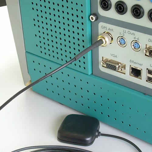
MENTOR-GPS/IRIG-B: The MENTOR 12 equipment allows for this synchronism by the use of two alternatives of very precise time reference inputs: GPS and IRIG/B. It requires the installation of the corresponding Printed Circuit Board. GPS and IRIG/B boards are plug & play; once the hardware has been detected and the signal is received, the unit is in disposition to initiate a state sequence or execute a COMTRADE file in a previously defined instant with a precision of microseconds. User can upgrade the MENTOR 12 with these optional boards at any time by themselves, without needing to send back the unit to factory.
Key Features
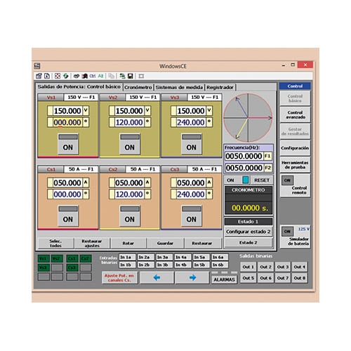
Power source controls
Measurement display: multifunction timer
Function keys: channel selection
Battery simulator: Auxiliary DC supply
I/O states: monitoring of power sources
On-screen access to Alarms reports.
Output Power trimmer
Fine/coarse tuning.
Real-time representation of power vectors.
Timer operation/trip setup and preferences
Event Logger
External measurement configuration
Hardware configuration and maintenance
10 years warranty.
Other Products

QUASAR
Three Phase Industrial Grade Protective Relay Test Set with cloud technology
Powerful and flexible
- 4 x 300V + 3 x 60A outputs, switchable to 7 current outputs
- 6 binary inputs + 4 binary outputs
- External DC current and voltage measurement
- 6 low-level outputs to test sensors, meters etc, and to upgrade with more channels
- Integral Wi-Fi, Ethernet LAN, dedicated IEC-61850 port and Expansion port
- Field serviceable
Rugged and portable
- 19.5 kg (43 lb)
- Integral ABS casing with wheels and extensible handle. No separate travel case needed.
Familiar User Interface
- Conduct quick or pre-configured tests directly from your tablet or smartphone
- Connect to your Windows computer for automated, exhaustive testing
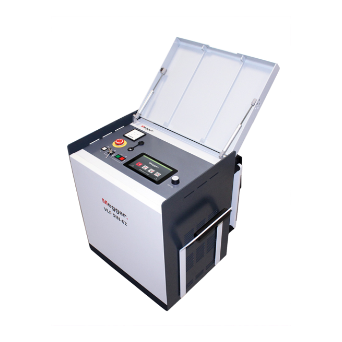
VLF SIN 62
VLF sine wave test system for medium voltage cables with integrated Tan Delta
- Performs cable withstand testing, cable diagnosis, and sheath fault pinpointing
- Smallest and lightest unit on the market in its class
- Unique user-experience, thanks to a large, colour touch screen
- Automatic result interpretation as per latest IEEE 400.2 standard
- High safety, thanks to its analogue residual voltage indicator
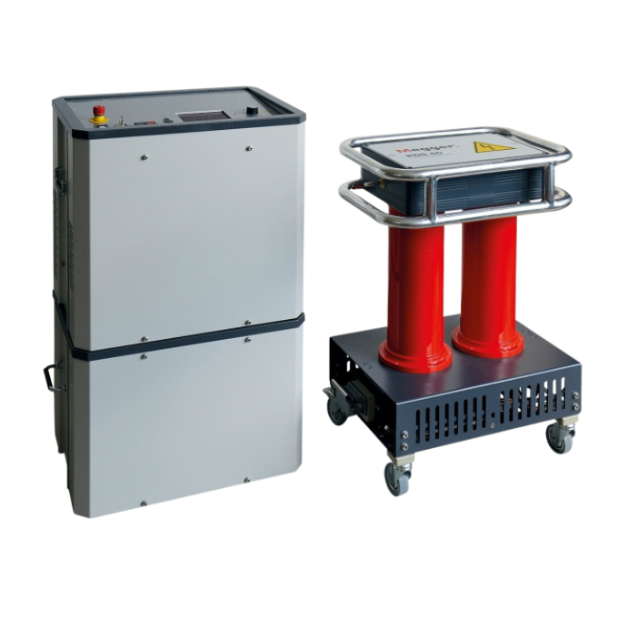
TDM 45
High power test and diagnosis combination for MV cables (Tan Delta, VLF and PD)
- Cable testing, cable diagnosis, and sheath testing in one device
- Enables standard compliant high power VLF testing at 0.1 Hz (5 µF at 40 kV RMS)
- Internal tan delta measurement with automatic result interpretation
- Partial discharge diagnosis using VLF sine wave, damped AC or 50/60 Hz slope technology voltages